The Ultimate Guide to DFM Casting Design: Rules, Ratios, and Defect Prevention (2026 Updated)
Are you struggling with high scrap rates, unexpected rework, or structural failures in your custom metal parts?
Ignoring casting physics during the initial CAD phase almost always guarantees costly issues like porosity in metal casting or severe warpage down the line. Why do perfectly modeled CAD parts fail on the foundry floor? I’ve seen countless projects hit delays and cost overruns because engineers prioritize pure geometry over actual manufacturability.
As an engineering partner at Vastmaterial, I know that a flawless, high-performance part doesn’t start on the foundry floor—it starts with bulletproof casting design.
In this post, you will learn exactly how to apply proven Design for Manufacturing (DFM) casting principles to your models. From hitting the exact casting wall thickness guidelines to mastering fillet radius rules, this is your ultimate technical checklist for 2026. Whether you need to eliminate shrinkage, optimize a permanent mold, or leave the perfect allowance for precision CNC machining, this guide will show you how to get it right the first time.
Core Principles of DFM in Casting Design
Effective casting design bridges the gap between digital models and physical reality. Incorporating DFM casting principles early in the engineering phase is not optional; these rules act as direct solutions to prevent critical manufacturing failures during solidification and cooling. To guarantee your parts survive the metal casting factory and meet performance specs, strictly enforce these foundational guidelines.
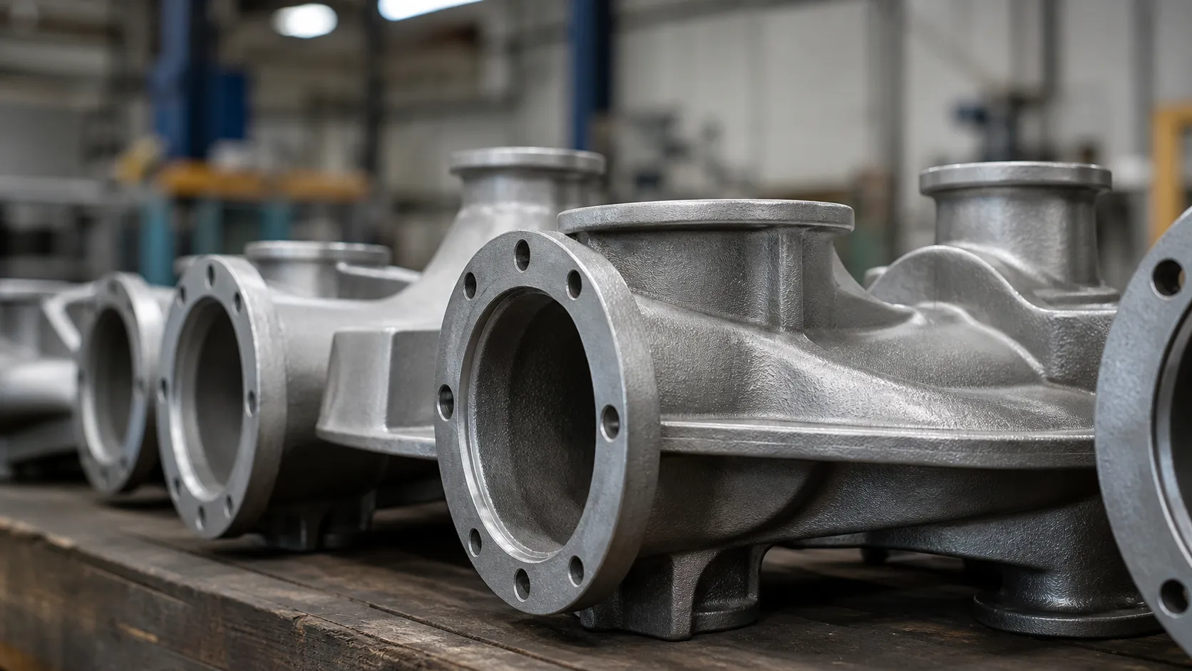
Casting Wall Thickness Guidelines
Uneven walls lead to uneven cooling rates. This thermal imbalance guarantees isolated hot spots, shrinkage voids, and severe warping.
- Maintain Uniformity: Keep wall sections as uniform as structurally possible throughout the entire part.
- Gradual Transitions: When a transition between thin and thick sections is unavoidable, use a gentle taper rather than an abrupt step.
- Core Out Heavy Masses: Hollow out thick geometries to maintain consistent thickness and prevent internal shrinkage defects.
Die Casting Draft Angles
A perfectly dimensioned part that gets locked inside a mold is a scrapped part. Draft is the calculated taper applied to vertical faces, allowing the part to release smoothly without damaging the tooling.
- Standard Taper: Always apply a minimum of 1° to 2° of draft to all vertical surfaces perpendicular to the parting line.
- Deep Draw Allowances: Deeper cavities and interior pockets require steeper draft angles to ensure clean ejection and prevent wall galling.
- Cycle Efficiency: Appropriate draft angles drastically reduce mold wear, speed up cycle times, and lower overall production costs.
Casting Fillet Radius Rules
In casting design, sharp internal corners are the enemy of structural integrity. They create severe localized stress concentrations, disrupt molten metal flow, and are the primary source of hot tears.
- Eliminate Sharp Intersections: Never leave a hard 90-degree internal corner in your CAD model.
- Apply Generous Radii: Use calculated fillets on all internal corners to distribute mechanical stress evenly and promote smooth metal flow during the pour.
- Round External Edges: Breaking sharp outside corners with a radius prevents edge chipping and localized cooling anomalies.
Optimizing Ribs, Bosses, and Parting Lines
We rely on ribs and bosses to increase structural stiffness and provide tapped mounting points. However, designing them incorrectly creates massive thermal defects. Proper parting line placement is equally critical for efficient gating and flash control.
Ribs and Bosses Casting Guidelines
| Feature | Design Rule | Failure Prevented |
| Ribs | Thickness must be 50% to 60% of the adjoining wall. | Surface sink marks and subsurface porosity. |
| Intersections | Stagger intersecting ribs into a “T” shape instead of a cross (“+”). | Heavy metal mass concentration and thermal hot spots. |
| Bosses | Connect isolated bosses to adjacent walls using ribs. | Poor metal feeding and localized shrinkage voids. |
Parting Line Placement and Gating Systems
Where the two halves of a mold meet is your parting line. Getting this right is the foundation of smart casting design. Poor placement forces complex draft angles and complicates the gating system (the "plumbing" that guides molten metal into the cavity).
Optimizing the parting line and gate locations early on guarantees fast cycle times, reduces material waste, and lowers unit costs, particularly for high-volume aluminum die casting services.
- Keep It Flat: Always aim for a straight, flat parting line. Stepped contours increase tooling costs and the risk of heavy flash.
- Isolate Critical Features: Move crucial sealing surfaces (like O-ring grooves) entirely into the solid block of the mold cavity, away from the seam.
- Plan for Trimming: Design the parting line on an outer edge where automated trim dies can easily shear the flash off.
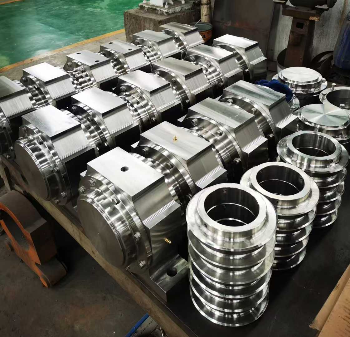
Material Selection for Custom Metal Casting Solutions
Picking the right metal is just as critical as getting the geometry right. Partnering with a proven precision casting foundry ensures you match the alloy to its operating environment.
High-Temperature Alloy Casting
For aerospace, military, and power generation parts facing extreme heat:
- Titanium Alloys: Offers an unbeatable strength-to-weight ratio and exceptional corrosion resistance.
- Superalloys: Nickel-based alloys maintain structural integrity and resist creeping at their maximum thermal limits.
Stainless and Alloy Steels for Strength
When sheer physical strength and impact resistance are the main goals:
- Stainless Steel: Provides excellent rust resistance, ideal for marine hardware, medical devices, or chemical processing.
- Alloy Steels: Engineered for rugged durability in heavy machinery and high-stress structural supports.
Aluminum and Copper Alloys
When the priority is weight reduction or energy transfer:
- Aluminum Alloys: Lightweight, highly machinable, and excellent for heat dissipation (heavily utilized in automotive).
- Copper Alloys: The undisputed champions for electrical and thermal conductivity, used for electrical contacts and heat exchangers.
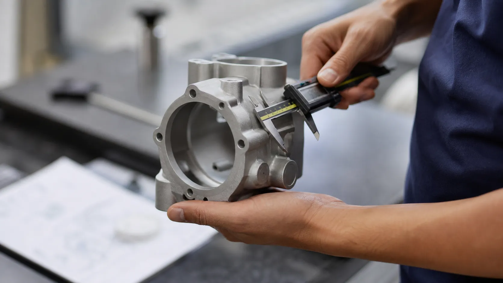
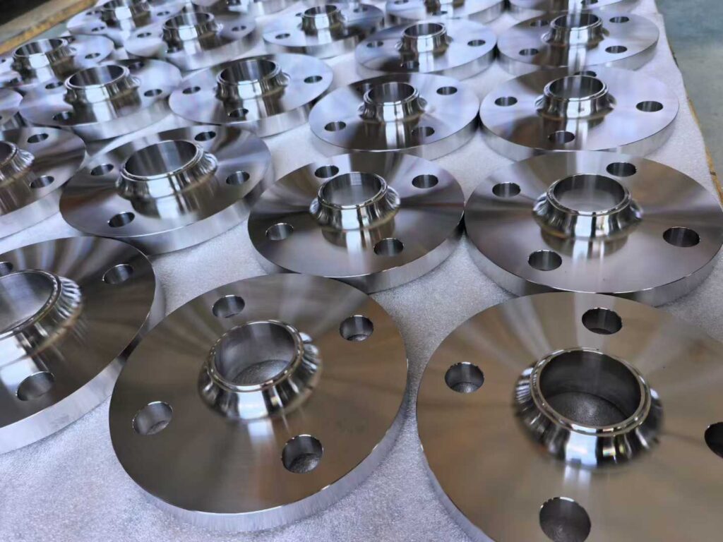
Secondary Operations: Precision CNC Machining for Castings
Even with optimized casting design, parts frequently require additional work to hit tight tolerances. In the US manufacturing sector, pairing a solid rough casting with precision finishing is the standard for high-performance components.
- Leave Sufficient Stock: Add enough extra material (machining allowance) so the cutting tool bites into solid metal, cleaning up the surface without leaving rough as-cast patches.
- Match the Process: Standard sand casting naturally requires a larger machining allowance than tighter processes like investment casting.
- Add Fixturing Points: Specifically design flat surfaces, heavy tabs, or tooling lugs that a CNC vise can grip securely without crushing the part.
- Establish Strong Datums: Define reliable, unmachined reference points so the machinist knows exactly where to zero their tools.
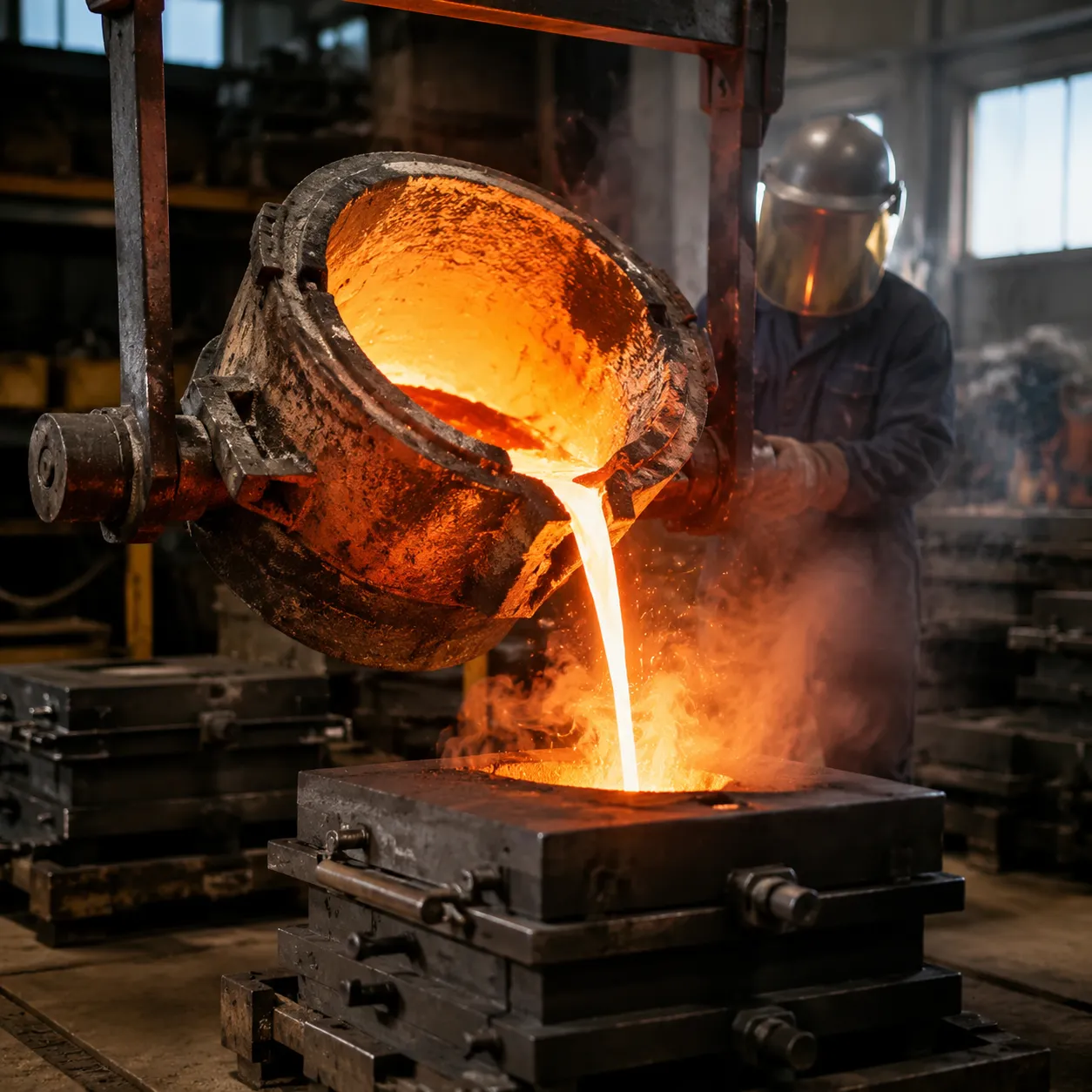
Leveraging Advanced Tech for Casting Defect Prevention
To deliver top-tier custom metal casting solutions, Vastmaterial relies heavily on advanced manufacturing technologies. The old “pour and pray” method does not cut it for manufacturers demanding defect-free parts.
Real-Time Monitoring and Casting Simulation Software
Before a single ounce of metal is poured, we validate the entire process virtually using simulation software:
- Flow and Fill Analysis: Simulating how molten metal enters the mold allows us to adjust gating to prevent turbulence and air entrapment.
- Solidification Mapping: By mapping thermal gradients, we predict where hot spots and shrinkage will occur, allowing us to place risers accurately.
- Stress Prediction: We identify areas of residual stress before they cause the physical part to warp or crack.
- Real-Time Foundry Monitoring: Sensor-driven monitoring tracks temperature, pressure, and cycle times on the foundry floor to guarantee the final part matches the engineering tolerances.
FAQ: Common Questions About Casting Design
What is the minimum wall thickness for metal casting?
Following standard casting wall thickness guidelines, the minimum depends on the metal and process. For traditional sand casting, aim for 0.10 to 0.15 inches. For high-pressure die casting, walls can be as thin as 0.04 inches. Keeping walls uniform is always the safest bet.
How do draft angles affect casting cost?
Ignoring draft angles drives up production costs. Applying proper die casting draft angles (1 to 2 degrees) allows the part to eject smoothly, speeding up cycle times, minimizing tool wear, and drastically lowering scrap rates.
Why are fillets important in casting design?
Sharp corners act as stress magnets. Sticking to casting fillet radius rules by rounding internal and external corners improves metal flow during the pour and prevents hot tearing as the part hardens.
What is the difference between porosity and shrinkage?
Both are major targets for casting defect prevention. Porosity is caused by trapped gas or air bubbles forming small holes inside the metal. Shrinkage happens naturally as liquid metal cools and contracts, creating voids if the gating system doesn’t feed enough extra metal.
How do I choose the right alloy for my casting project?
Your choice boils down to application: Do you need high tensile strength, extreme heat resistance, or electrical conductivity? Reviewing specific casting alloy properties based on your operating environment ensures top-tier performance and cost-efficiency.