An investment casting draft angle is the slight taper on vertical walls that lets a fragile wax pattern leave the injection die without tearing, scuffing, or losing casting tolerances. Most external faces need only about 0.5° to 1.5°, while deep pockets and cores need steeper relief because wax shrinkage grips internal pins. This guide covers standard angle ranges, when true zero draft is feasible, tooling and geometry trade-offs, design practices for parting lines and fillets, and common scrap modes when draft is wrong.
Why Investment Casting Draft Angle Matters for Wax Patterns
Draft angles define the success of the initial tooling stage. In precision lost-wax casting, we do not pour metal directly into rigid metal dies; we inject sacrificial wax first. The investment casting draft angle provides the essential taper on vertical walls that allows that fragile wax pattern to release cleanly from the aluminum or steel injection die. Without an intentional taper, friction binds the pattern to the die cavity, compromising part accuracy before the ceramic shell mold is even created.[1]
Role of Draft Angles in Damage-Free Wax Pattern Removal
Wax expands under injection pressure and contracts as it solidifies. Without a proper mold release angle:
Vacuum pockets form behind deep vertical faces, resisting pattern ejection.
Wax adheres to raw tooling walls, causing surface scuffing and drag marks.
Mechanical ejector pins push through soft wax instead of releasing the part cleanly.
Preventing Pattern Distortion, Tearing, and Micro-Cracking
When tooling grips a pattern during ejection, the structural integrity of the wax is ruined. We see these failures on the shop floor every day when draft angles are neglected:
Pattern Distortion: The force of mechanical ejection bends thin ribs, warping functional datum points out of true casting tolerances.
Tearing: High friction along tall vertical features rips delicate profiles right off the runner system.
Micro-Cracking: Sub-surface tensile stress cracks form in the wax. These hidden fractures transfer straight into the ceramic slurry, creating metal flash, inclusion defects, or catastrophic part failure during the metal pour.
Investment Casting vs. Sand Casting vs. Die Casting
Investment casting offers unmatched design freedom and near-net shape capability, requiring far less taper than traditional methods such as investment casting vs sand casting or investment casting vs die casting routes.
| Casting Method | Typical Draft Angle | Tooling Contact Material | Primary Reason for Draft |
|---|---|---|---|
| Investment Casting | 0.5° to 1.5° | Tooling steel/aluminum to soft wax | Protects delicate wax from tearing and distortion |
| Sand Casting | 1.0° to 3.0° | Rigid pattern to compacted sand | Prevents sand mold walls from crumbling upon pattern draw |
| Die Casting | 1.0° to 2.0°+ | Hardened steel cavity to molten metal | Resists severe thermal grip as solidifying metal shrinks onto the core |
Because wax exhibits natural lubricity and thermal contraction away from outer cavity walls, we can work with much tighter angles than sand or high-pressure die casting. However, designing with zero taper without a specialized strategy remains a high-risk gamble.
Standard Investment Casting Draft Angle Guidelines
In our foundry, we treat the investment casting draft angle as a functional feature rather than an afterthought, balancing clean ejection against final machining needs.
External Vertical Faces: 0.5° to 1.5°
External walls are the easiest to release because cooling wax contracts away from the cavity walls.
- Standard external walls: A 0.5° to 1.0° draft is sufficient for most standard exterior surfaces under 50 mm in height.[2]
- Tall vertical faces: For heights exceeding 50 mm, bumping the draft to 1.5° prevents surface scuffing during ejection and extends the working life of the wax injection die.
- Low-profile geometries: Shallow exterior steps under 10 mm can occasionally get by with 0.25°, provided the die cavity is highly polished.
Deep Pockets, Blind Holes, and Internal Cores: 1.5° to 3°
Internal cavities require much steeper draft angles. Because wax shrinks toward its center as it cools, it grips tightly around any stationary steel cores or internal mold pins.
- Blind holes and shallow recesses: Require a minimum of 1.5° to avoid tearing the pattern during pull-out.
- Deep pockets and internal ribs: Need 2.0° to 3.0° of draft to counteract shrinkage pressure and ensure clean core extraction without distortion.
- Through-holes: Whenever possible, we split cores from both sides to reduce the necessary draw depth and draft angle. For broader design rules, consult our precision metal casting guide for engineers and OEM buyers.
Draft Angles Based on Draw Depth and Height Ratio
The deeper the draw, the more friction the wax pattern encounters during ejection. We use these standard ratios to determine minimum draft allowances:
| Feature Type | Feature Depth / Height | Recommended Draft Angle | Key Consideration |
|---|---|---|---|
| External Wall | Up to 25 mm | 0.5° | Wax shrinks away from cavity |
| External Wall | 25 mm to 100 mm | 1.0° - 1.5° | Prevents drag marks on long pulls |
| Internal Pocket | Up to 25 mm | 1.5° | Wax contracts onto the core pin |
| Deep Core / Cavity | Over 25 mm | 2.0° - 3.0° | Eliminates wax breakage and die sticking |
Applying these standard tapers early in your 3D CAD modeling prevents expensive die modifications, minimizes pattern scrap rates, and preserves true near-net-shape tolerances.
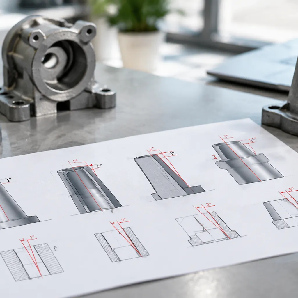
Can You Cast with Zero Draft Angle in Investment Casting?
Yes, you can achieve a true zero draft angle (0°) in investment casting, but it changes how we handle your tooling and process your wax patterns.[3] Standard rigid injection dies need tapers to eject wax patterns cleanly. When your part geometry demands strictly vertical walls with zero draft casting features, we bypass standard mechanical ejection using specialized tooling configurations and sacrificial inserts.
Scenarios Where True Zero Draft (0°) Is Technically Feasible
Zero draft is practical under specific production conditions:
- Short vertical draw lengths: Shallow faces under 12 mm (0.5 inches) where thermal wax shrinkage pulls the material naturally inward and away from cavity walls.
- External surfaces aligned with open pull directions: Features where sliding die segments or side actions pull straight back perpendicular to the face before pattern ejection.
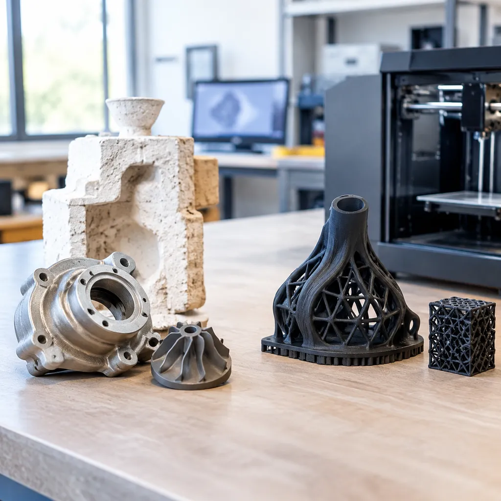
- Additive pattern workflows: Tool-less manufacturing routes. When prototypes or low-volume runs bypass rigid dies completely, checking our casting 3D printing guide for clean burnout and zero-ash resins shows how sacrificial printed patterns produce perfectly vertical walls without any draft penalty.
Soluble Cores, Ceramic Inserts, and Collapsible Dies
When geometry locks a zero-draft wall inside a pocket or internal passage, standard metal tooling pulls are impossible. We solve these geometry traps with three primary methods:
- Multi-Piece Collapsible Metal Dies: Segmented mechanical cores collapse inward mechanically before pull-out, freeing straight internal faces without dragging across the wax.
- Soluble Wax Cores: We inject an initial core using water-soluble wax, place it inside the primary wax die, shoot the regular pattern around it, and dissolve the core in a mild acid or water bath.
- Pre-Formed Ceramic Cores: For high-temperature alloys and complex zero-draft internal channels, we insert rigid ceramic cores directly into the wax pattern tooling. The ceramic remains in place during shell building and metal pouring, dissolving away chemically after cast solidification.
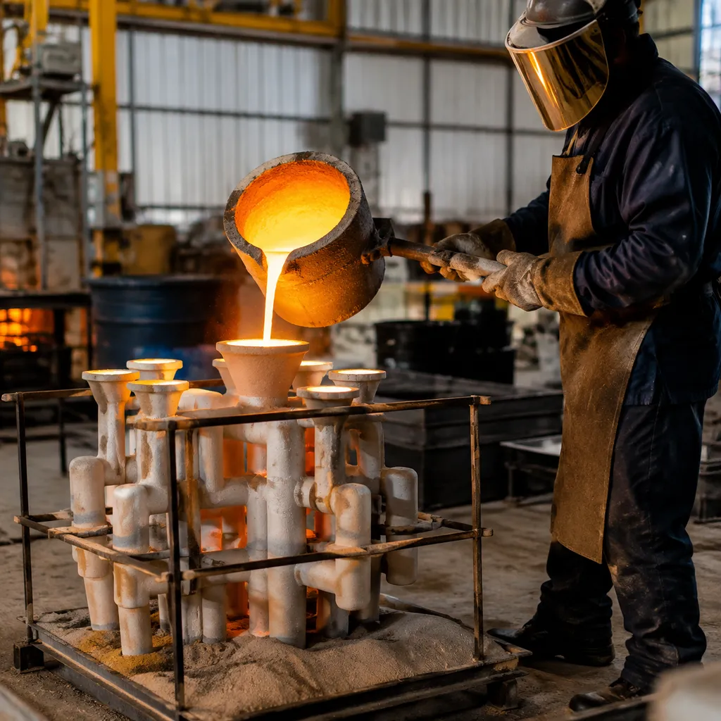
Tooling Complexity, Scrap Rates, and Cost Trade-Offs
Eliminating the investment casting draft angle always introduces operational trade-offs. Weighing tooling capital against secondary machining helps determine if zero-draft tooling makes economic sense:
| Tooling Approach | Draft Capability | Tooling Cost Multiplier | Cycle Time & Scrap Impact |
|---|---|---|---|
| Standard CNC Aluminum Die | 0.5° to 1.5° required | 1.0x (Baseline) | Fastest injection cycles, minimal scrap |
| Collapsible Mechanical Die | True 0° possible | 1.8x - 2.5x | Higher die maintenance, moderate cycle time |
| Soluble Wax Core System | True 0° internal/external | 2.2x - 3.0x | Double injection cycle, higher handling scrap |
| Leachable Ceramic Core | True 0° complex passages | 3.0x - 4.5x | Specialized post-cast leaching, highest unit cost |
Key Takeaway: If your design strictly requires 0° faces to eliminate post-machining allowances, collapsible tooling or sacrificial cores deliver net-shape results. If minor surface taper does not compromise assembly, retaining a standard 0.5° draft preserves lower tooling costs and reliable production yields.
Factors That Set Your Investment Casting Draft Angle
Choosing the right investment casting draft angle isn't a guessing game. On the foundry floor, setting taper angles comes down to how pattern waxes cool, how tooling cavities are machined, and how intricate your part geometry really is. We balance these four critical variables to lock in clean pattern ejection without compromising near-net-shape accuracy.
Wax Shrinkage Rates and Thermal Contraction
Pattern wax behaves differently depending on whether it is cooling against an internal pin or an external cavity wall:
- Internal features grip tooling: As wax cools, volumetric wax shrinkage pulls material tightly onto internal cores and pins. These surfaces require an aggressive draft angle (typically 1.5° to 3°) to prevent tearing during pattern ejection.
- External walls shrink away: Wax naturally shrinks away from outer cavity faces, meaning external vertical surfaces need much less taper (often 0.5° to 1°) for clean release.
- Volumetric shifts: Thicker sections cool slower, driving localized contraction that increases drag forces against die walls.
Tooling Material Choices and Cavity Polish
The friction between the cooling pattern and the wax pattern tooling dictates how much draft you must design into the part:
| Tooling Variable | Aluminum Dies | Hardened Steel Dies |
|---|---|---|
| Cavity Polish | Readily polished to mirror/SPI finishes | Can achieve higher diamond polishes with longer wear life |
| Thermal Dissipation | Fast, uniform cooling; reduces cycle times | Slower cooling; holds heat longer on deep walls |
| Minimum Draft Impact | Often requires 1.0° on deep draws to avoid galling soft aluminum | Allows tighter tapers (down to 0.5°) on polished straight draws |
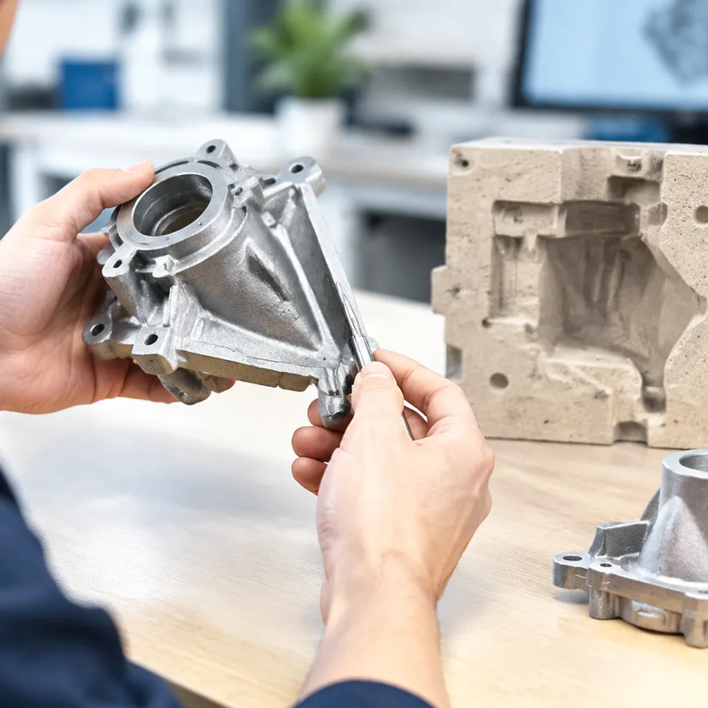
Part Geometry, Wall Thickness, and Deep Ribs
Uniform wall thickness is the benchmark of good design for casting. Sudden cross-sectional transitions create differential cooling rates, warping straight edges and locking vertical walls against the tooling.
Deep, narrow ribs present the biggest hurdle. As tooling draw depth increases, mechanical friction multiplies along the vertical stroke. We add progressive draft to tall ribs - widening the root and tapering toward the tip - to ensure patterns pop free without cracking. Where draft adjustments cannot bridge the gap to tight final tolerances, planning ahead with stainless steel CNC machining allows us to cast standard draft profiles and clean up critical datum faces later.
Surface Finish and Release Agent Behavior
Rougher die finishes generate mechanical interlocks with the wax. If a cavity requires textured EDM finishes or matte textures, the required mold release angle climbs immediately to prevent scuffing.
Liquid or aerosol mold release agents help reduce ejection force, but they can pool at the bottom of steep, zero-draft pockets. Adequate draft ensures release agents coat vertical walls uniformly without puddling, protecting fine surface finishes and preventing wax distortion run after run.
Design Practices for Investment Casting Draft Angles
Getting the investment casting draft angle right isn't just about making wax patterns slip out of the tooling easily. It is about protecting component function and keeping production costs down. We focus on a few proven design rules to optimize wax pattern tooling without compromising the final component geometry.
Strategic Parting Line Placement
The quickest way to cut down on unnecessary tapers is smart parting line design. We split the wax injection die along natural edges, centerlines, or non-critical cosmetic boundaries:
- Split the draw depth: Splitting the part along its centerline cuts the vertical wall depth in half. Shallow cavity depth means you need less taper to eject the pattern safely.
- Keep critical flats isolated: By placing parting lines along functional faces, we keep those surfaces perpendicular, shifting draft requirements entirely to non-functional walls.
- Minimize witness marks: Strategic placement prevents parting flash across critical sealing faces or mounting interfaces, preserving your net shape.
Blending Draft Angles into Fillets, Ribs, and Bosses
Draft angles should never look like an afterthought. We blend tapers naturally into the geometry using smooth radii and fillets:
- Structural ribs: Taper ribs slightly from base to tip (typically 1° to 1.5°). This promotes clean wax mold release while encouraging directional solidification when pouring molten metal.
- Mounting bosses: Apply external tapers directly into the boss body, blending the root into adjacent walls with generous fillets to prevent stress concentrations.
- Feature integration: When choosing the best metal for casting, blending these transitions evenly ensures uniform shell buildup and prevents localized hot spots.
Balancing Draft with Post-Machining Allowances
Where a perfectly flat, zero-degree surface is mandatory for mating parts, rely on secondary finishing rather than forcing zero draft on the wax tool.
| Design Strategy | Tooling Impact | Machining Impact | Best Used For |
|---|---|---|---|
| Add Draft to Machining Stock | Standard open-and-shut die | Clean cleanup cut | Mating faces with tight flatness tolerances |
| Draft in the "Plus" Direction | Low-wear, simple cavity | Minimal face milling | Bearing seats and locating stops |
| Draft in the "Minus" Direction | Preserves clearance envelope | Light edge deburring | Clearance pockets and non-mating recesses |
Add the taper into your post-machining allowances. Ensure the minimum cut depth cleans up the high point of the drafted wall completely, eliminating tool chatter during CNC operations.
Communicating Draft and Datum References on 2D Drawings
Unclear drawings cause scrap. We always define draft behavior clearly on the drawing to avoid manufacturing disputes:
- Specify draft direction: Clearly note whether the draft adds material (+), removes material (-), or splits across the nominal dimension.
- Protect datum targets: Datums should sit on flat, non-drafted features or specific targeted points. Never define a datum along a drafted surface without specifying the exact contact height.
- Explicit drawing notes: Use standard callouts such as "All unspecified vertical faces require 1° draft angle maximum, adding material away from parting line." This keeps toolmakers aligned with functional casting tolerances.
Common Issues Caused by Incorrect Investment Casting Draft Angles
In our foundry runs, insufficient taper creates immediate friction during the wax extraction stage, triggering cascading failures across the entire production cycle.
Wax Pattern Breakage, Drag Marks, and Tooling Wear
When a wax pattern lacks adequate relief along vertical walls, friction takes over the moment the die opens:
- Torn and Broken Patterns: Without clearance, the cooling wax binds against metal cavity walls, snapping delicate bosses, ribs, and thin sections during ejection.
- Surface Scuffing and Drag Marks: Insufficient taper drags the wax face against the tool, scoring the smooth finish and degrading final cast surface quality.
- Tool Cavity Galling: Forcing vacuum-locked patterns out of straight-walled dies accelerates mechanical wear on aluminum or steel tooling, rounding sharp corners and ruining fine parting line integrity over time.
Dimensional Distortion and Shell Building Failures
The damage rarely stops at visual blemishes. Improper draft angles fundamentally warp component stability:
- Pattern Warpage: Uneven ejection forces twist and bend the pattern as the ejector pins push against stuck sections, introducing permanent dimensional deviations before dipping even begins.
- Inconsistent Ceramic Slurry Coating: Scuffed or micro-cracked wax surfaces disrupt standard slurry wetting. Air bubbles get trapped in surface tears, causing premature slurry breakdown or localized shell spalling during dewaxing.
- Metal Infiltration Defects: Any micro-tear in the wax pattern transfers directly to the ceramic shell mold, inviting liquid alloy runout, flash, or heavy inclusion defects during the pour.[4] Drawing from our precision casting insights and material performance benchmarks, stable pattern extraction remains the absolute baseline for predictable metallurgy.
Higher Scrap Rates and Secondary Machining Overhead
Zero-draft or under-drafted parts quickly become budget killers:
| Problem Area | Direct Impact on Floor Operations |
|---|---|
| Foundry Yield | Spikes in cracked wax clusters directly slash primary mold yield before metal is poured. |
| Rework Costs | Extensive hand-finishing, blending out drag marks, and welding casting pits drain operator hours. |
| Machining Stock | Distorted cast walls require oversized post-machining stock allowances, turning a near-net-shape casting into an expensive secondary CNC milling job. |
Frequently Asked Questions About Investment Casting Draft Angles
What is the absolute minimum draft angle practical for investment casting?
In standard production, we recommend a minimum investment casting draft angle of 0.5° on external vertical faces. While 0.25° can work for very shallow features with high-polish dies, going below 0.5° significantly raises the risk of wax pattern tearing, surface scuffing, and costly tooling wear.
Does investment casting always require draft angles on every vertical surface?
No, draft is not strictly mandatory on every single face. We routinely achieve true zero draft (0°) when designs demand it, but it requires specialized tooling approaches such as:
Collapsible metal cores
Soluble wax cores
Pre-formed ceramic cores
Multi-piece mechanical side-actions
These methods eliminate the draft requirement by releasing the feature without dragging against the die wall during extraction. For standard tooling setups, adopting proper angles alongside advanced waxes investment casting parts ensures consistent pattern integrity and dimensional repeatability across production runs.
How does surface texture inside the wax die affect required draft?
Die surface finish directly dictates how easily the pattern releases. A mirror-polished die cavity (typically SPI A1 to A3) minimizes friction, allowing us to utilize minimal draft (0.5° to 1°). Conversely, rougher, textured, or EDM-finished tooling faces grip the cooling wax tightly; vertical walls on these finishes require at least 1.5° to 3° of draft to prevent heavy drag marks and pattern distortion.
Can 3D-printed wax patterns bypass draft angle limitations?
Yes. Rapid tooling and additive manufacturing - such as 3D-printed wax or polymer patterns - completely bypass standard draft angle limitations because there is no rigid injection mold to pull the pattern from. We use this approach frequently during low-volume prototyping and complex geometries, fully realizing a investment casting lost wax process that features true vertical walls, sharp undercuts, and zero-draft interfaces without specialized metal dies.
References
- Wikipedia - Investment casting (lost-wax process overview) ↩
- Investment Casting Institute - Casting Design Presentation (draft often ~0.5° per side) ↩
- Manufacturing Processes - Investment Casting (draft optional; wax-die release vs ceramic shell) ↩
- Investment Casting Institute - Industry association home ↩